Tuning Simulation to Match the Physical Cell
Even though industrial robots are highly precise machines, they often lack absolute accuracy compared to their simulated counterparts. Factors such as manufacturing imperfections and wear can cause a robot’s end-effector to miss its target by a few millimeters, even when using the same joint values as in simulation. Small imperfections in the lengths of the links or the angles of the joints can accumulate and affect the accuracy of the TCP (Tool Center Point).
Another source of inaccuracies is the location and orientation of conveyors and pallets in a palletizer cell. These components might slightly deviate from their positions in robot cell CAD models or their intended locations in simulation. Additionally, although robot cells should ideally be placed on level floors, slightly uneven floors can result in noticeable discrepancies between simulation and reality during motion executions.
When using the Jacobi palletizer and platform, motions are planned in advance using precise kinematic calculations. However, discrepancies between simulation and reality can negatively impact the performance of these motions. Therefore, it is crucial to minimize these discrepancies as much as possible.
Probing Tool Design
Probing is a calibration technique used to bridge the gap between simulation and reality. It involves moving the robot to key locations in its workspace and verifying the accuracy of these locations in the simulation. These locations typically include the lower corner of the conveyor and the corners or center of each pallet.
Probing utilizes tools that attach to and enclose the robot’s end-effector. In robotic palletizing, there is no off-the-shelf, one-size-fits-all tool available (as end-effectors come in all shapes and sizes), so you will need to design your own.
Consider a probing tool as an enclosure around the robot gripper, providing an added layer of protection when making contact with surfaces at probing points. The exact geometry of the probing tool must be known to obtain transforms from the robot flange to the contact points between the tool and the probing surface. It is also recommended that your probing tool consists of two main physical parts connected by passive compliance, such as springs. This design allows the compliant part of the end-effector to align with the probing surface when there are rotational deviations between the probing surface and the end-effector.
To design a probing tool that fits your robot end-effector, follow these general guidelines:
Obtain Dimensions: Measure the dimensions of the end-effector or obtain them from a CAD model.
Design Primary Enclosure: Using CAD software, design an initial enclosure for your robot end-effector. For a vacuum end-effector like the one shown below, this would typically be a rectangular casing.
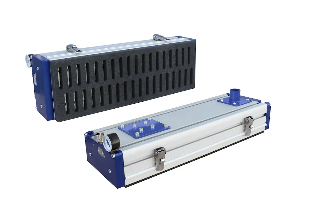
Design Compliant Component: In CAD software, design a secondary piece for the probing tool. This piece should attach to the primary enclosure using springs or other passive compliance mechanisms. Determine the type of passive compliance to use and create the attachment mechanism, such as holes for attaching springs.
Determine Attachment Method: Decide on a method to attach the probing tool to the end-effector. For vacuum grippers, the probing tool can be attached by activating the vacuum. For other types of grippers, a strap or similar attachment method may be necessary.
Calibration Process
To calibrate the robot to its environment, follow these steps:
Reduce Robot Speed: Reduce the robot speed to a minimum to reduce the risk of damage. If you have models in your controller to enforce collision avoidance, consider disabling them so you can move the tool closer to specific points in space that may be near obstacles.
Attach Probing Tool: Secure the probing tool to the gripper. For vacuum grippers, activate the suction to ensure the probing tool is tightly aligned with no air gaps. For non-vacuum grippers, use straps or other attachment methods to ensure the probing tool is securely fastened.
Obtain Transforms from Robot Flange to Probing Tool’s Corners: Determine the transform from the robot flange to its TCP using CAD models or by measuring with a tool such as a ruler or caliper. Then, determine the transforms from the end-effector’s TCP to each corner of the probing tool using the same methods. Finally, calculate the transforms from the flange to the probing tool’s corners by multiplying the individual transforms.
Probe the Environment: Identify key probing points critical to the palletizing task. Jog the robot end-effector to the designated probing points, positioning the probing tool to match the desired orientation as closely as possible. Use the compliant portion of the tool to rotationally align the end-effector with the probing surface. For each probing location, note down the joint values of the robot from the robot controller. For center measurements of pallets, determine the positions of all corners and calculate the central position based on the pallet dimensions.
Input Data in Studio: Enter the joint values for each probing point into Jacobi Studio. Use the previously calculated transform to determine the pose of each probing tool corner in the simulation. Create temporary waypoints for these poses and visually verify their accuracy. For probing points at the conveyor or pallet corners, use Studio’s measurement tool to measure the distance between the waypoints and the corresponding corners.
Adjust Conveyor or Pallet Poses in Sim: If discrepancies exist between the probing point locations in simulation and in real life, adjust the poses of the conveyor or pallet in the simulation to match the real-life positions. Always modify the simulation to match reality, not the other way around.
Verify Calibration Accuracy: Arrange a simple palletizing test, such as placing a single box in the center of a pallet. Run the palletizer application (instructions in the following section). Use calipers or other measurement tools to verify the distances between the end-effector or box and the target positions, ensuring precise alignment with the intended locations.