Part 1: Configuring a Cell in Studio
The Jacobi Palletizer workflow begins in Jacobi Studio. Studio is an easy-to-use robotic visualization tool for setting up and managing projects that leverage the Jacobi Motion Library.
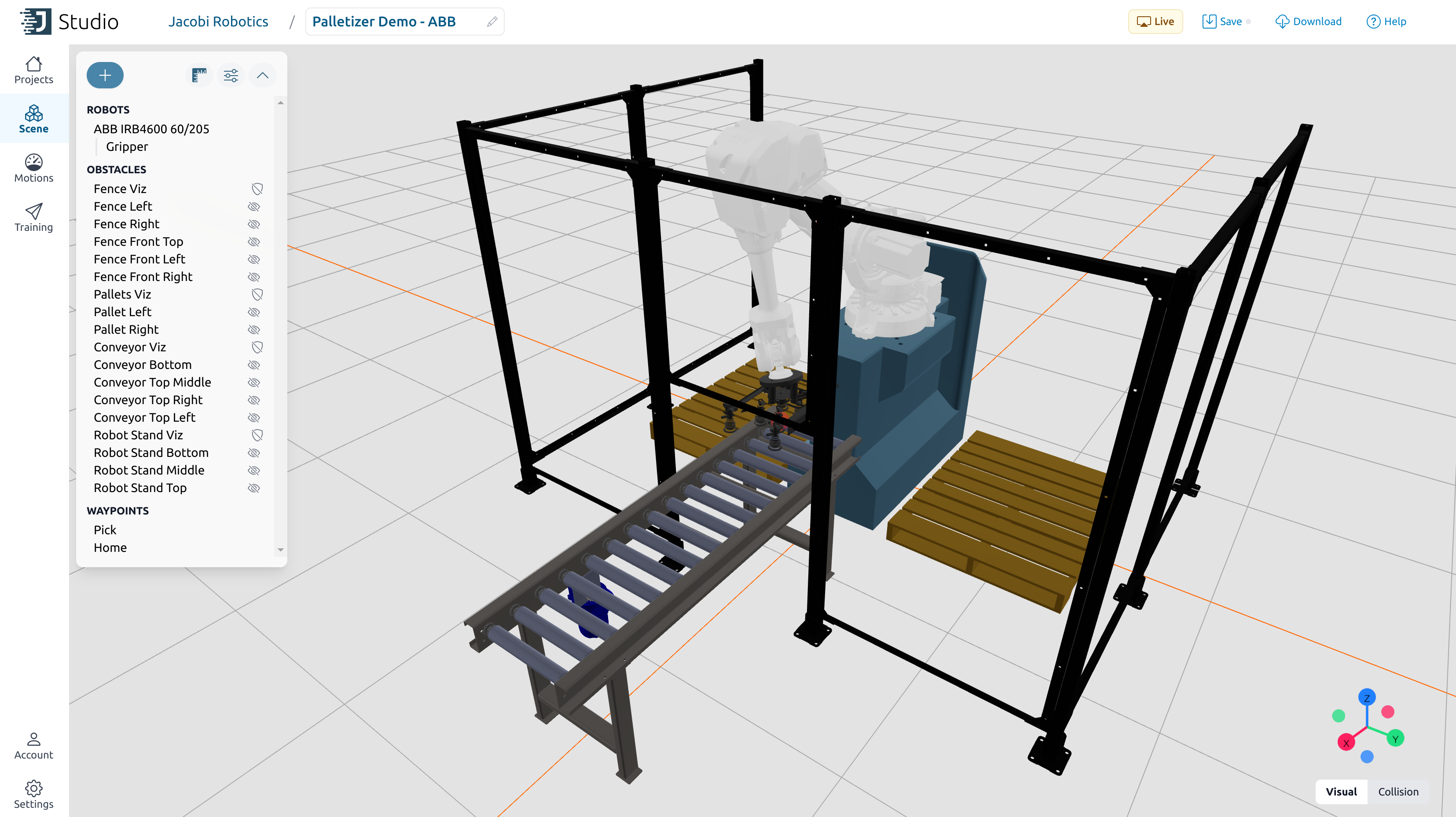
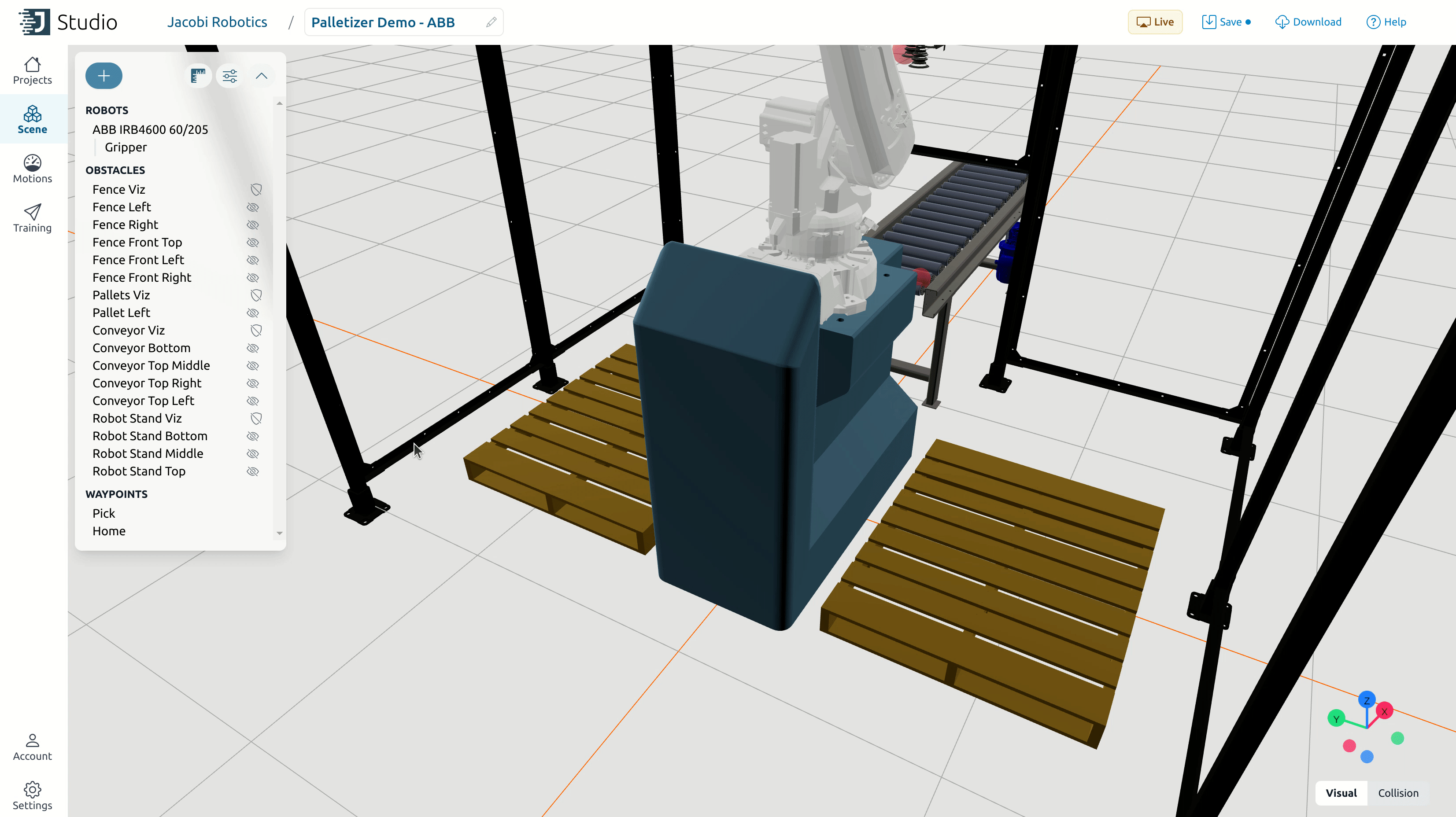
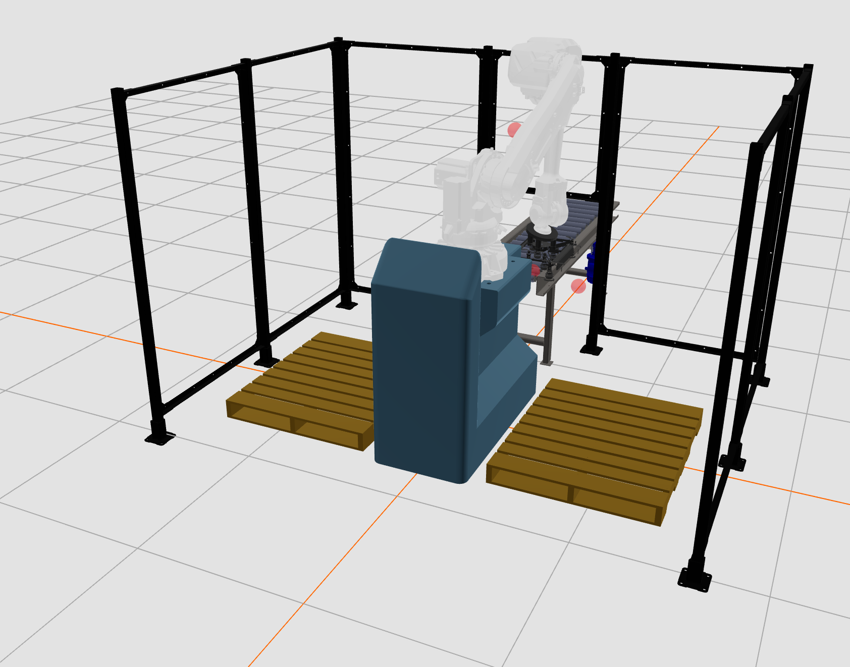
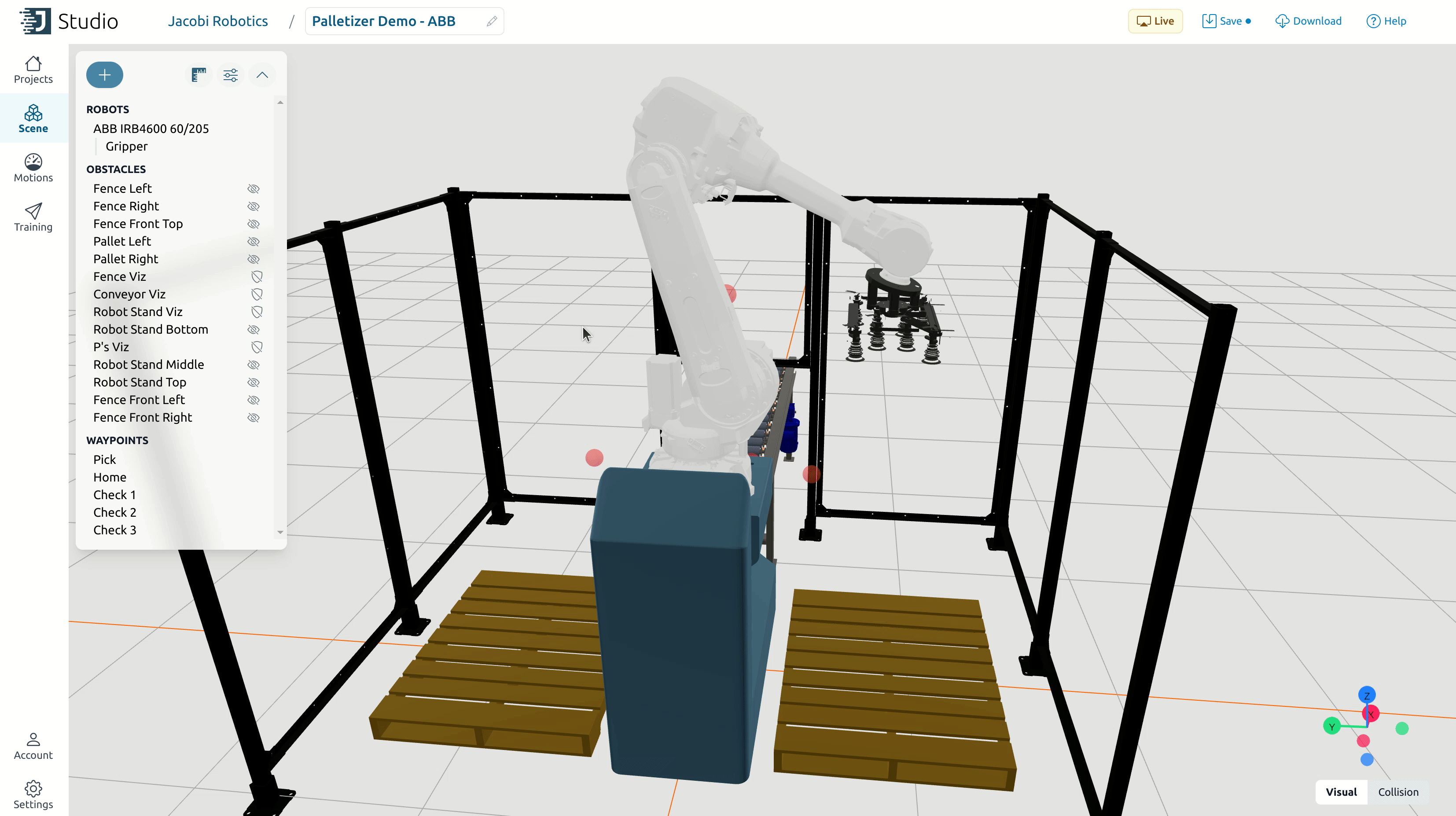
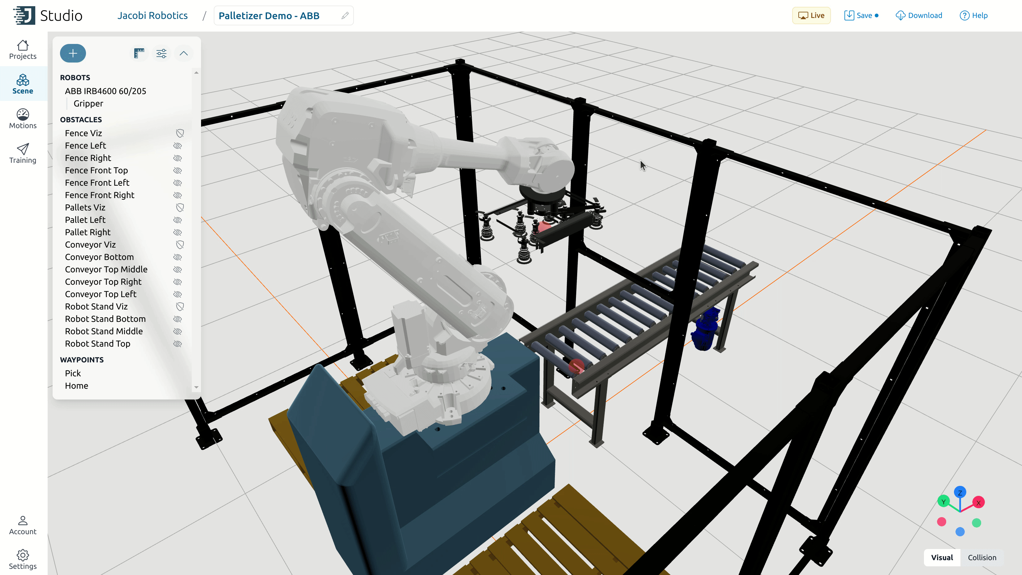
Projects in Studio encompass all necessary configurations for defining a robotic cell, including selecting the robot model, setting up the environment, adding obstacles, and specifying waypoints. An example palletizer cell project in Studio is shown below.
To start, head to the Jacobi Studio site, log in with your Jacobi account credentials, and create a new project (by clicking on “New Project”).
To explore the example cell shown above, download its .jacobi-project file here and import it into Studio by clicking the import button next to “New Project”.
Robot
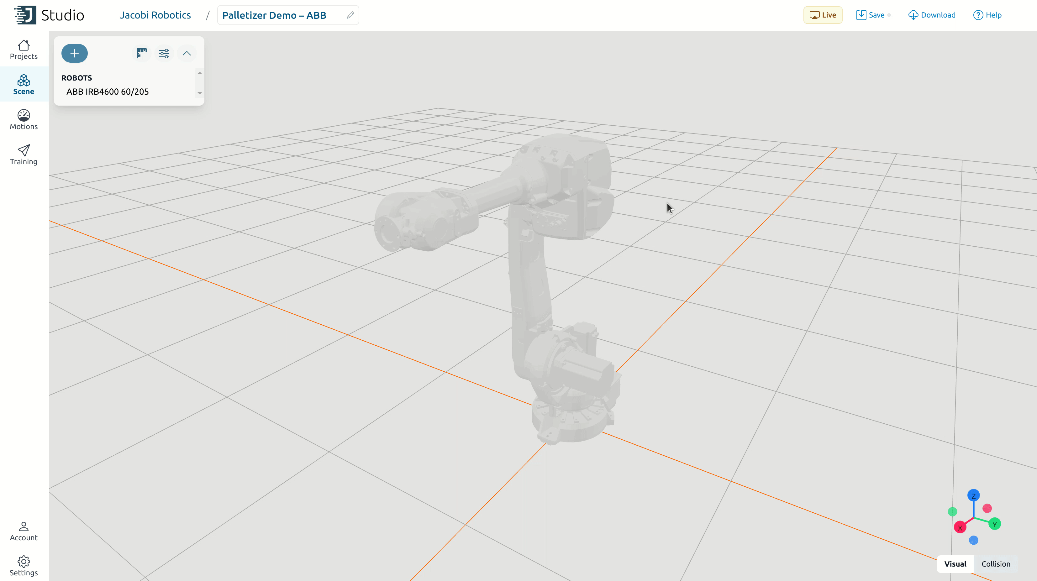
In the new Studio project, add a robot by clicking on the plus sign button at the top-left corner of the screen, selecting “Add a robot…”, and choosing the appropriate robot model. Common palletizer robot models include the ABB IRB4600 60/205, Yaskawa HC20, Universal Robots UR20, FANUC M-20iB/25, and KUKA KR70 R2100.
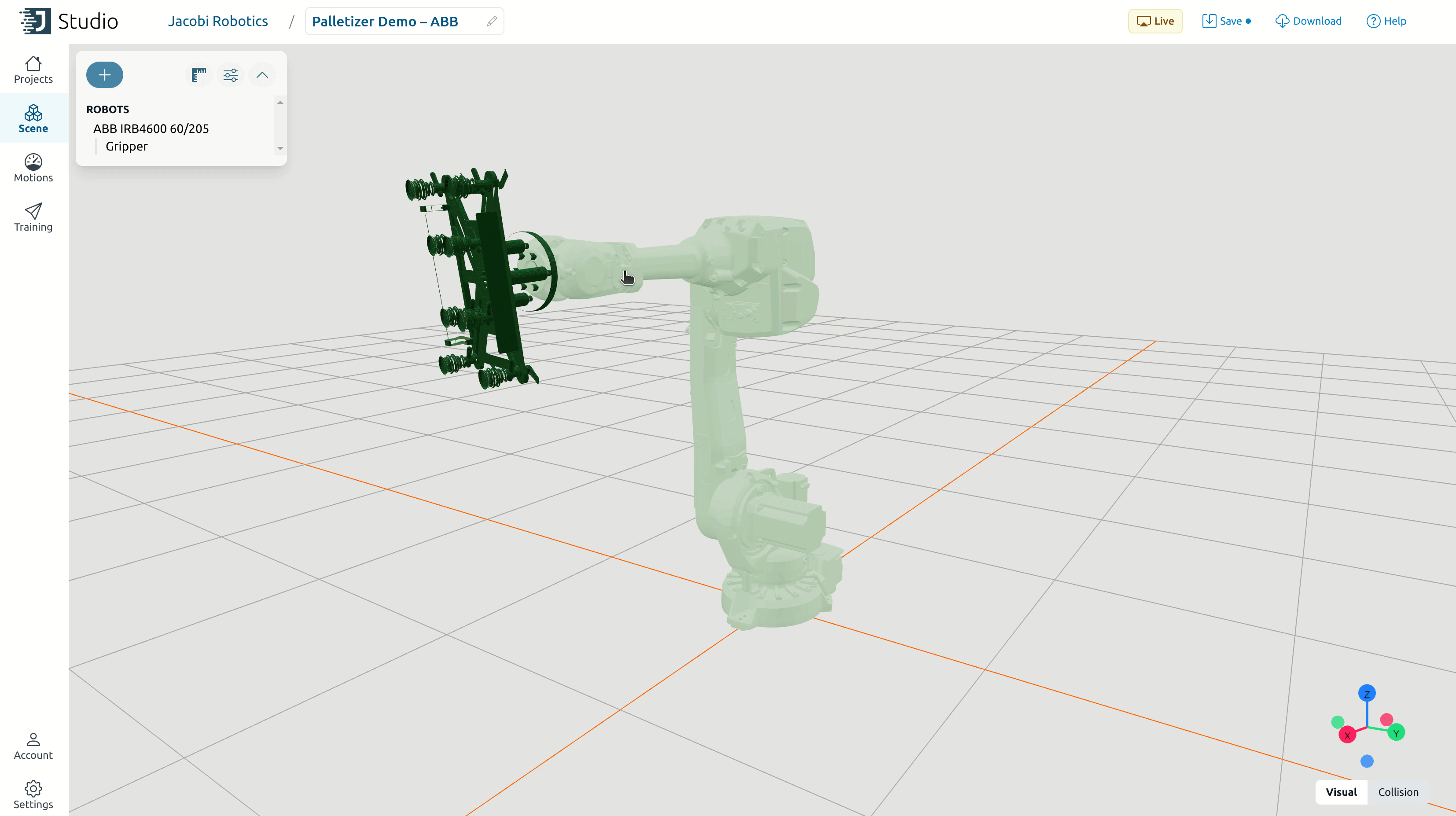
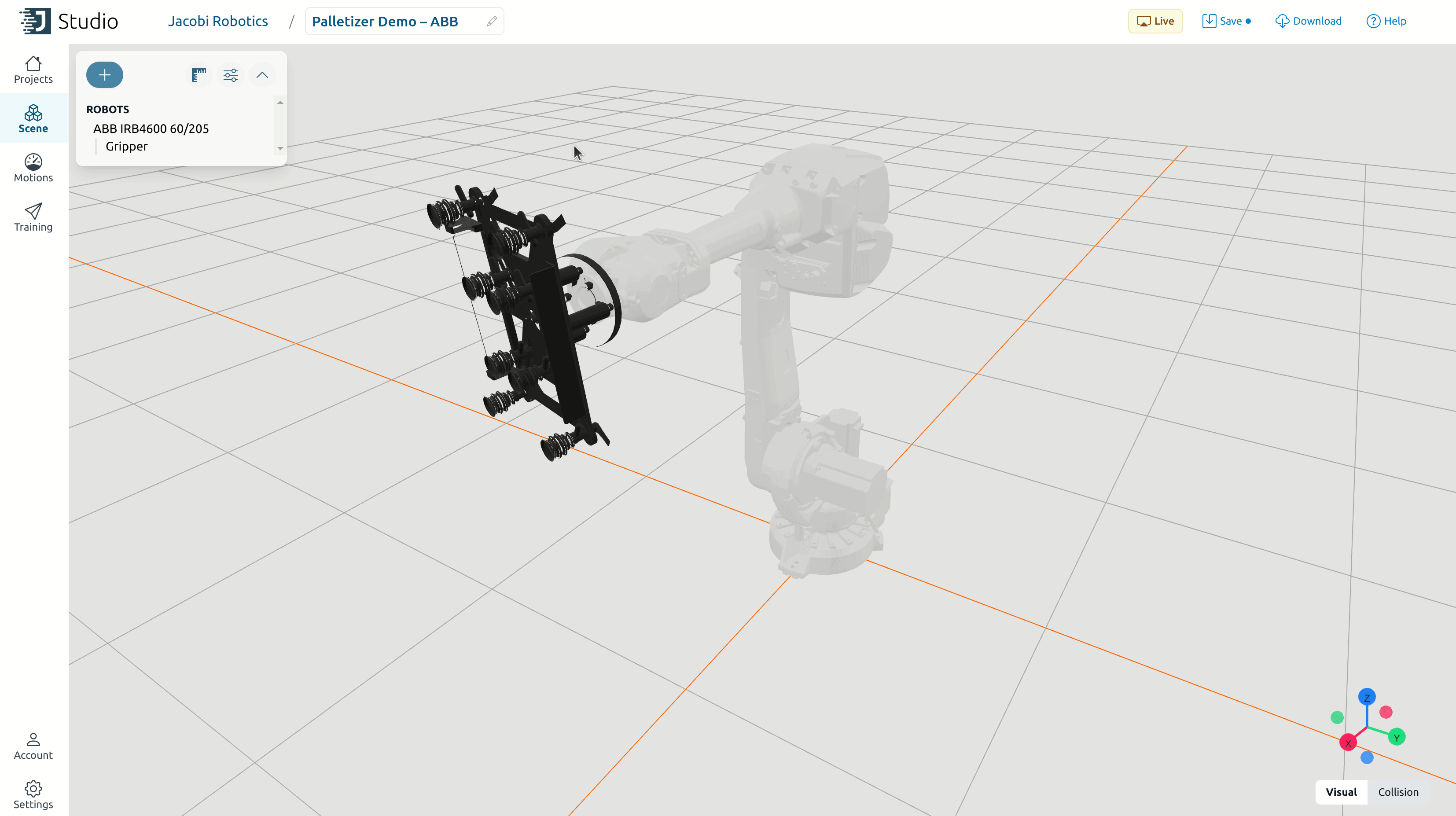
Obtain a 3D mesh file (.glb or .obj format) of your end-effector and attach it to the robot in Studio by selecting the robot and navigating to “End Effector” > “Add Obstacle” > “Upload a .glb or .obj obstacle” in the robot popup. If needed, adjust the gripper’s position and orientation (defined in the flange coordinate frame) by modifying the values in the gripper popup or by using the transform gizmo. You can edit the object’s color by clicking on the paint bucket icon.
Tip
Notice in the GIF above that the end-effector obstacle’s scale parameter is modified to 0.001. This adjustment is sometimes necessary because unit data isn’t always transferred correctly.
In the example above, a millimeters-to-meters conversion was needed. Watch out for this issue when importing mesh files and be prepared to adjust the scale parameter accordingly.
Next, enter the values for the flange-to-TCP (tool center point) transform, which you can obtain from CAD software or physical measurements of the gripper.
Attention
Often, this transform involves a positive Z translation and a 180-degree rotation in X. The 180-degree rotation is necessary because the flange points downwards when the robot palletizes boxes, and we want the TCP frame to be right-side-up when traversing waypoints.
In the example below, a more complex flange-to-TCP transform was needed due to the end-effector’s angled geometry.
To adjust the robot joint limits, click on “Limits” in the robot popup. Make sure the joint limits in Studio do not exceed those of the physical robot.
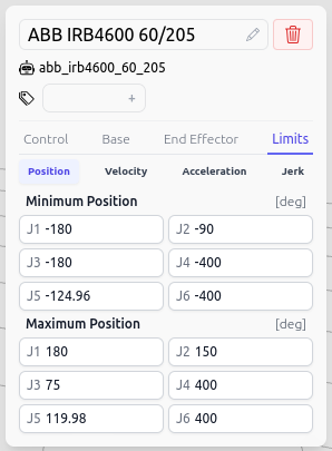
Tip
Oftentimes, the joint limits in Studio should be more constrained than the manufacturer’s limits to prevent awkward motions, movements close to obstacles, or collisions with the robot’s end-effector. Constraining position in joints 3 and 5 specifically proves beneficial for these reasons.
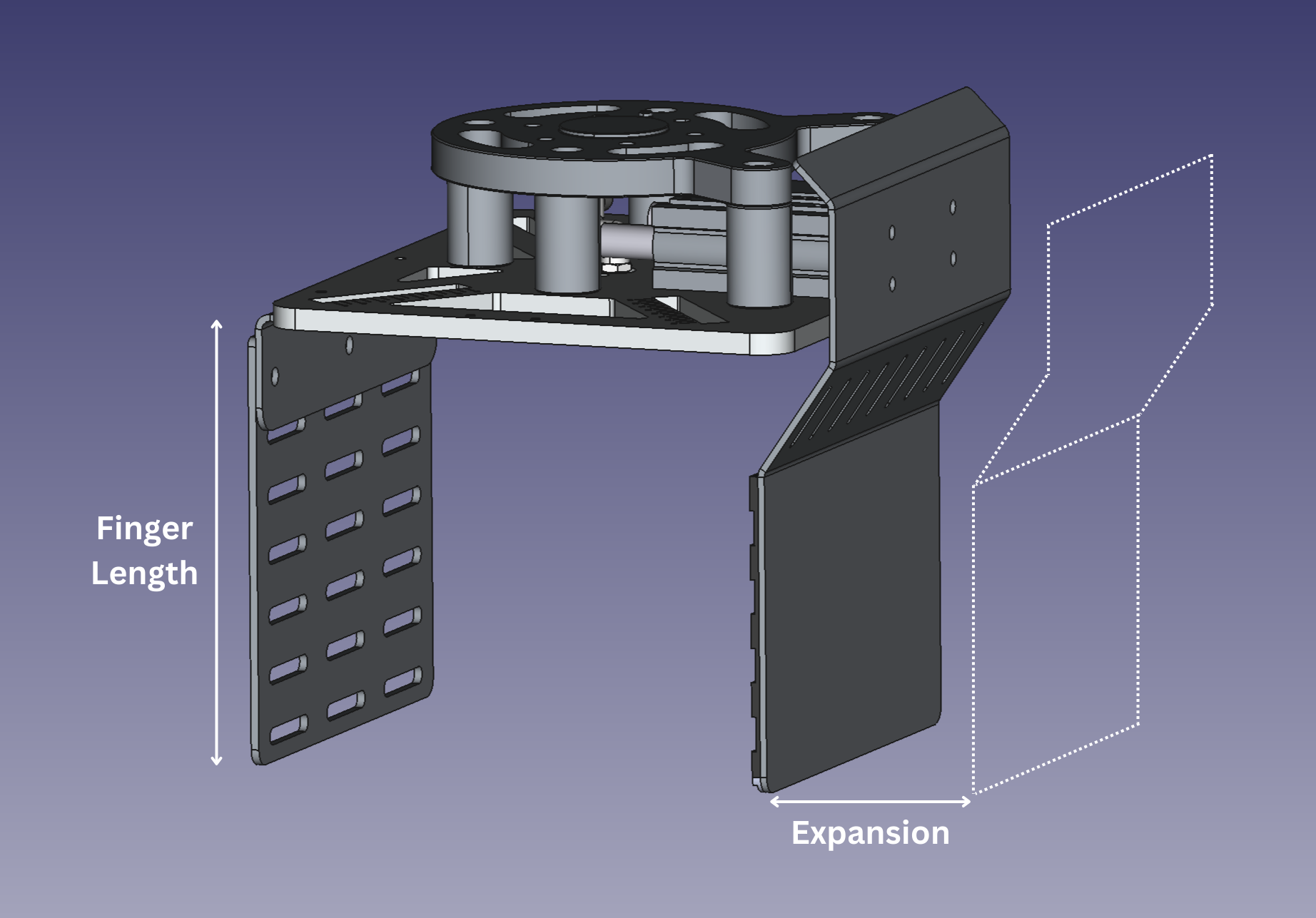
Clamp
If you are using a gripper with a clamp, add the following tags to the end-effector obstacle (by clicking on the tag icon and inputting the desired value):
clampgripper-finger-length=[GRIPPER-FINGER-LENGTH]If your clamp gripper contains suction cups as well, this distance corresponds to the end of the suction cup to the end of the finger.
gripper-expansion=[GRIPPER-EXPANSION-LENGTH]This is the distance that the clamp can move when opening and closing.
Environment
Note
In this guide, the term “base” refers to the robot’s base link or base frame. This is distinct from any external stands, pedestals, or mounts that the robot might be placed on.
Add a robot stand by clicking on the plus sign at the top-left corner of the page, selecting “Upload a *.glb or *.obj obstacle”, and importing the corresponding mesh file. If you do not have a model of a stand, try adding a box instead.
Adjust the position and orientation of the robot stand by entering the appropriate values in the obstacle popup or by using the transform gizmo.
When adding a robot, its base is positioned at the world origin. After adding a stand, you can either position it below the robot base or make the stand sit at the world origin and move the robot up. The latter approach is recommended as it simplifies tracking the ground floor. To do this, select the robot in the Scene menu on the left and adjust the values in the “Base” section to position the robot on top of the stand.
Add other elements such as the conveyor, pallets, and fencing to the robot scene by following the same steps as for the robot stand.
Pallets
You have just added pallet obstacles using mesh files. However, these obstacles will only serve for visualization purposes. The palletizer application requires pallet obstacles to be defined as box obstacles. To meet this requirement:
Add a box obstacle.
Position the box obstacles to align with the existing pallet models.
Add a
Pallettag to each box obstacle.Disable collisions for the visual mesh obstacles by clicking the shield icon in the Scene Tree next to the name of the pallet.
Hide the box obstacles by clicking the eye icon for each pallet obstacle in the Scene menu.
Below is a GIF showcasing the workflow for creating the right-side pallet in the example cell. In this project, the visual pallet obstacles are combined into a single obstacle called “Pallets Viz,” while the “Pallet Left” and “Pallet Right” are the actual pallet box obstacles. These box obstacles have collisions enabled but are hidden for visual clarity.
Custom Collision Models
When uploading an object in Studio, its collision model is generated using convex hulls. For complex geometries, especially those that are concave or have internal cavities, collision models based on convex hulls tend to be inaccurate (and oftentimes significantly larger than the actual object). In such cases, it is more effective to disable collisions on the original object file and instead create custom collision models using Studio’s simple geometries (like boxes and cylinders) to accurately enclose the obstacles (similar to what is done with Pallets).
Tip
When creating custom collision models, make these geometries slightly larger than the actual objects to provide an additional guardrail against collisions.
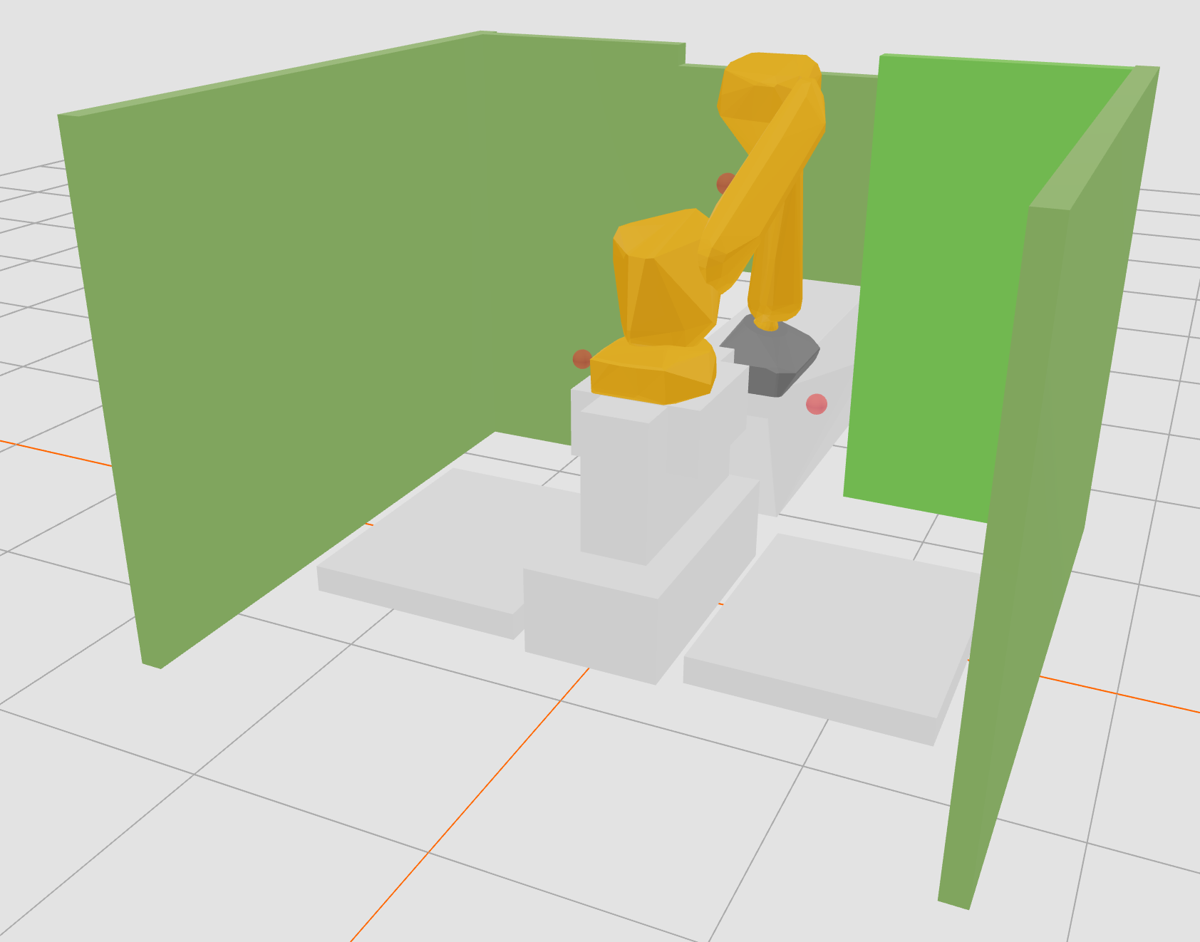
Below are the visual and collision views of the example cell used in this guide. Custom geometries were created for the robot stand, conveyor, pallets, and cell fence. You can view the collision view of your cell by selecting “Collision” at the bottom-right corner of the screen.
Waypoints
Waypoints are predefined positions and orientations that guide a robot’s movements.
To create a new waypoint, click on the plus sign at the top-left corner of the screen and select “Add a waypoint…”. The waypoint will appear at the robot TCP’s current position and orientation.
Your Jacobi Palletizer project must contain two waypoints: a “pick” waypoint and a “home” waypoint.
Pick Waypoint
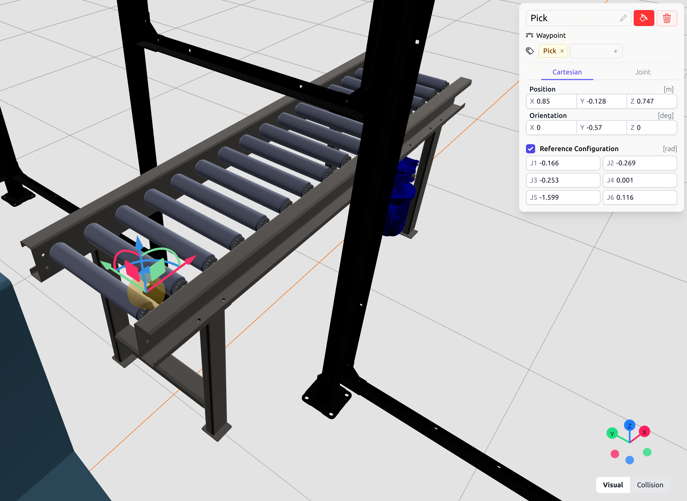
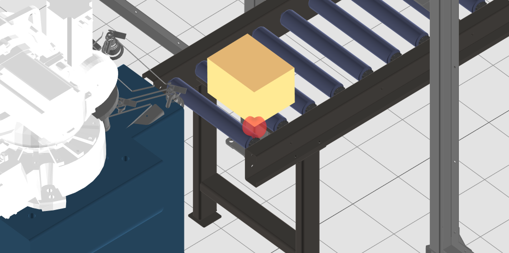
Create a new waypoint for the “pick” position and tag it as Pick. This waypoint should not be located at the pick position on the box. Instead, you should align it with the bottom-right corner of the box, or the corner nearest to the conveyor’s edge, assuming the boxes are aligned to the right side of the conveyor. Ensure the waypoint is clear of any obstacles by using the Collision view of Studio. Refer to the yellow waypoint in the visualization below for the pick waypoint in the example cell.
Box sizes are configurable (details provided in the next section), and the application uses the pick waypoint as a starting reference point for the box. The positive axes of the waypoint indicate the location of the box. The image below visualizes the box in relation to the pick waypoint in the example cell.
Add a reference configuration to the pick waypoint by checking the “Reference Configuration” box and entering the values. A reference configuration is a set of joint space positions that guide the inverse kinematics calculations in the right direction. When multiple inverse kinematics solutions exist, specifying a reference configuration ensures the robot joints are positioned accurately.
Tip
Instead of entering the reference configuration values manually, you can also:
Move the robot’s TCP to somewhere around the target location using the transform gizmo.
Visually confirm that the joint configuration of the robot looks appropriate.
Check the “Reference Configuration” box in the waypoint screen. Values for the robot’s current joint configuration will be populated there.
Verify that the robot’s end-effector can reach the waypoint and that its position and orientation are correct by selecting “Pick” from the “Jump to” dropdown in the robot’s control panel, as shown below. Again, this is not the actual pick point on the box but it is a good practice to see how the robot looks like at the waypoint.
Home Waypoint
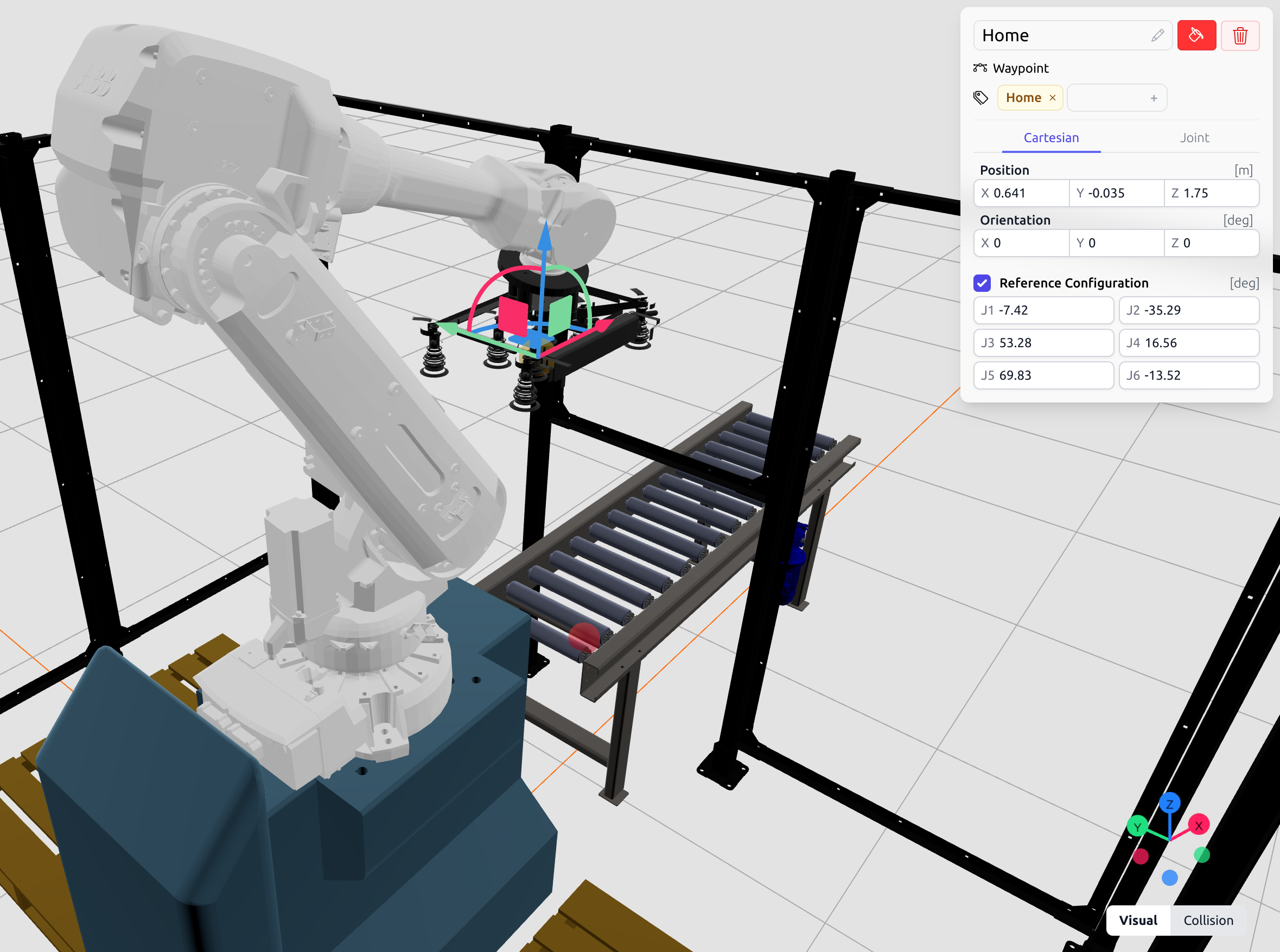
Create a new waypoint for the “home” position and tag it as Home. This waypoint should be collision-free even with a grasped box and a box on the conveyor. Again, add a reference configuration to know exactly how the robot looks at home, without the ambiguity of inverse kinematics. Use the “Jump to” feature to verify the robot’s location and orientation at the waypoint.
Tip
A good practice is to set the home waypoint at twice the height of the tallest box (plus a small safety margin) above the pick waypoint. This allows the robot to move to the home waypoint even with a grasped box and a box on the conveyor. Feel free to choose any other safe location if this specific one is not collision-free in your cell.
For the example cell, the home waypoint looks like:
Maintenance Waypoint
Optionally, define a maintenance waypoint with a Maintenance tag. A maintenance waypoint is useful for positioning the robot for easy access during routine checks, repairs, or adjustments.
Downloading the Project
Once you have completed configuring your project in Jacobi Studio, download the .jacobi-project file by clicking the “Download” button at the top-right corner of the screen. This file is necessary for proceeding to the next section.
Tuning Simulation to Match the Physical Cell
For running the application on a physical cell, refer to this page for detailed guidance on tuning your Studio simulation to closely match the physical cell.
Additional Documentation on Jacobi Studio
If you would like a more in-depth look at other features Jacobi Studio has to offer, head to the Studio documentation.